Image Details
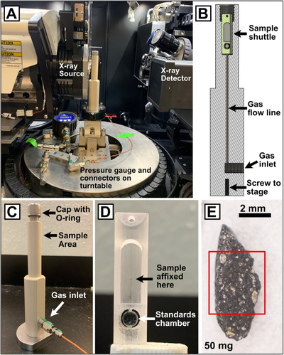
Caption: Figure 1.
Experimental setup and sample. (A) Experimental setup in the Zeiss scanner showing the mounted sample rig, pressure gauge, and connectors on the turntable below. (B) Cutaway of CAD drawing of PEEK sample rig showing the location of the gas inlet, internal gas flow line, and shuttle (green) inserted into the sample area. (C) Labeled photograph of the PEEK sample rig. (D) Photograph of the sample shuttle showing areas where the chip is held and the standards chamber below it. (E) Photograph of the Murchison USNM 5487 chip that was mounted in the sample shuttle for the experiment. The red box indicates the scan subvolume.
Other Images in This Article
Show More
Copyright and Terms & Conditions
© 2026. The Author(s). Published by the American Astronomical Society.