Image Details
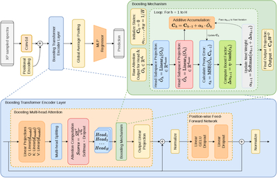
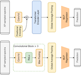
Caption: Figure 3.
The schematic diagram of the boosting-transformer model. The top-left panel illustrates the overall structure of the model; the bottom panel shows the detailed structure of the core module, the boosting-transformer encoder layer; and the top-right panel shows the iterative structure of the boosting mechanism.
Other Images in This Article
Show More
Copyright and Terms & Conditions
© 2026. The Author(s). Published by the American Astronomical Society.
Copyright ©
2026 Astronomy Image Explorer. All Rights Reserved.