

Image Details
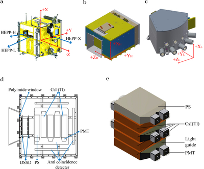
Caption: Figure F10.
Coordinate reference frames and internal configuration of the CSES-01 satellite and HEPP instruments. (a) Schematic of the CSES-01 satellite platform and its primary reference frame (x, y, z), where the +x-axis aligns with the flight direction, the −z-axis points toward the zenith, and the +y-axis completes the right-handed orthogonal system (facing the Sun). (b)–(c) Schematics of the HEPP-H (b) and HEPP-L (c) instruments; local coordinate systems are defined with xH/L-axes parallel to the satellite x-axis frame and yH/L- and zH/L-axes rotated within the y–z plane by 20∘ and 12∘, respectively. (d) Cross-sectional view of the HEPP-H assembly illustrating the arrangement of DSSDs, PS trigger layer, CsI(Tl) crystals, and peripheral anticoincidence detectors. (e) 3D structural diagram of the calorimeter, comprising one PS and four CsI(Tl) layers coupled to PMTs for signal readout.
Other Images in This Article
Show More
Copyright and Terms & Conditions
© 2026. The Author(s). Published by the American Astronomical Society.

