

Image Details
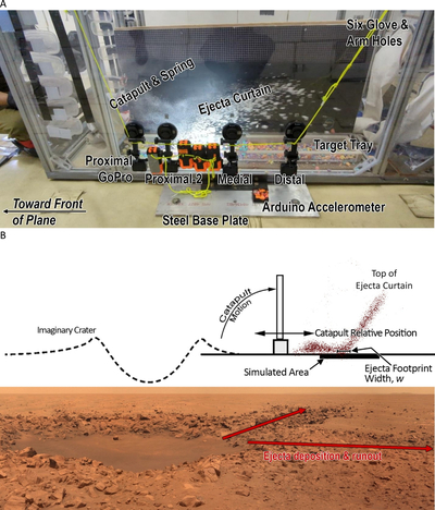
Caption: Figure 1.
(A) Overview of the science glovebox and ejecta catapult (mostly obscured) installed in Zero-G Corp.’s aircraft, G-Force One. Note the ejecta curtain, composed of white-colored crushed chalk, flying from left to right. Crushed chalk pieces of various colors from previous experiments are visible along the bottom of the clear-sided target tray and make up the regolith bed for the present experiment. The glovebox (dimensions 72 × 33 × 30 inches; 182.88 × 83.82 × 76.2 cm) features six gloved arm holes, GoPro cameras, and battery-operated LED lights affixed externally. The catapult system is intended to simulate an equivalent distance of a few crater radii from a hypothetical crater, especially around the continuous-to-discontinuous ejecta transition zone. The aircraft flew parabolic profiles to recreate approximate gravitational accelerations for the Moon and for Mars/Mercury (which have the same gravity). Modified from K. D. Runyon et al. (2025). (B) Schematic of the arrangement between the catapult, ejecta, and the imaginary crater, with the variable w illustrated. The catapult simulates some portion of the ejecta deposit within a few crater radii and especially around the continuous-to-discontinuous transition zone. Below the schematic is a mirror-flipped image of Concepcion Crater, Mars, to show a correspondence between the crater and ejecta. Modified from K. D. Runyon & O. S. Barnouin (2018), image credit: NASA/JPL-Caltech/Cornell/color mosaic by James Canvin/The Planetary Society.
Other Images in This Article

Show More
Copyright and Terms & Conditions
© 2026. The Author(s). Published by the American Astronomical Society.

