Image Details
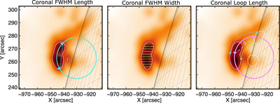
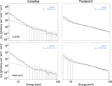
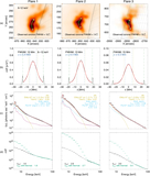
Caption: Figure 6.
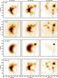
Example of how coronal source dimensions were determined from imaging. All panels show the 6–12 keV CLEAN image for Flare 1. Left: the length of the coronal source was determined by fitting a circle of radius r to the source and calculating the length of the arc between the contours, indicated with the arrows, using the chord of length a. Middle: measuring the width of the coronal source FWHM at several points to determine the average width. Right: the length of the coronal loop being measured from looptop to footpoint, as indicated by the pink arrow, using the length of chord S. Upper (blue arrow) and lower (green arrow) coronal loop lengths were determined by fitting a circle to the outer and inner loops, respectively. This panel includes contours of the footpoint emission in white.
Other Images in This Article
Show More
Copyright and Terms & Conditions
© 2026. The Author(s). Published by the American Astronomical Society.