Image Details
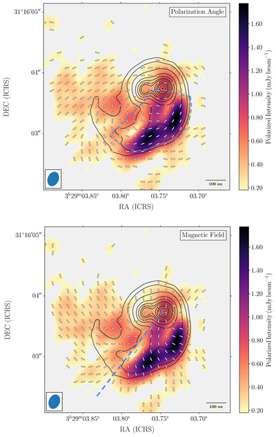
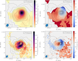
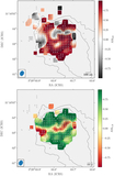
Caption: Figure 2.
Upper panel: the polarization position angle map from the SVS 13A polarized dust continuum emission as white pseudovectors. In color scale, we show the polarized intensity emission imaged using robust = 0.5, and in contours, we show the total intensity dust continuum imaged with robust = −2 and using levels of 10, 15, 28.7, 54.9, 81.1, 110, 130, 160, 190, 210, 240, and 260 mJy beam−1. The blue oval indicates the beam obtained by imaging the data with robust = 0.5. The blue segmented lines indicate the region where the polarization position angle appears to follow the spiral substructure seen in the dust emission. Lower panel: following the upper panel, the inferred magnetic field morphology map is shown under the assumption of grain alignment by magnetic fields (i.e., pseudovectors rotated by 90°). The blue segmented line indicates the region where the inferred magnetic field lines appear to bifurcate.
Other Images in This Article
Show More
Copyright and Terms & Conditions
© 2025. The Author(s). Published by the American Astronomical Society.