Image Details
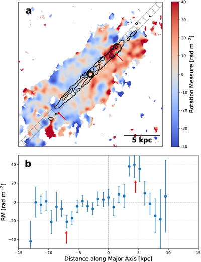
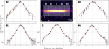
Caption: Figure 3.
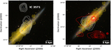
RM distribution along the major axis of NGC 4565. (a) The RM map overlaid with S-band total intensity contours (black lines, levels at 30σ, 40σ, 60σ, and 120σ; see Figure 1(c)) to highlight the inner radio ring structure. The rectangular boxes indicate the 15″ × 15″ bins used to extract the RM profile. (b) The RM profile along the major axis. Each data point represents the inverse-variance-weighted mean RM within the bin. The x-axis represents the distance from the galactic center, where negative values correspond to the southeast side. In each panel, the red arrows mark the positions of the local maximum (∼4.5 kpc, NW) and local minimum (∼−7 kpc, SE).
Other Images in This Article
Copyright and Terms & Conditions
© 2026. The Author(s). Published by the American Astronomical Society.