Image Details
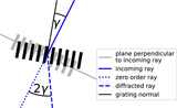
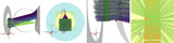
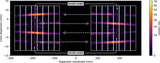
Caption: Figure 2.
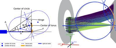
Left: Sketch of a tilted Rowland torus geometry shown in the plane of the optical axis and the symmetry axis of the torus. Photons arrive from the left. The location of the mirror is shown as a blue box. The optical axis (solid blue line) is offset from the center of the Rowland circle (blue square). The symmetry axis of the torus is marked as a blue long-dashed line. The torus is formed by rotating the blue circle around this line. To help visualize the 3D position of the torus, blue dotted lines are shown connecting the two circles. α is the angle between the optical axis and the line from the point where the optical axis intersects the Rowland torus (A) to the center of the Rowland circle. β is the angle from optical axis to the line connecting A to the “hinge”—the other point in this plane where symmetry axis of the torus and the Rowland circle intersect. Right: Visualization of a ray-trace of the same geometry. Colored lines show the path of individual rays starting on the left. Rays detected in the zeroth order are shown in green; blue and purple represent higher orders. Optical axis and the axis of the Rowland torus are indicated in blue and the location of detectors in orange, matching the sketch in the left panel.
Other Images in This Article
Copyright and Terms & Conditions
© 2024. The Author(s). Published by the American Astronomical Society.