

Image Details
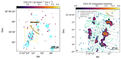
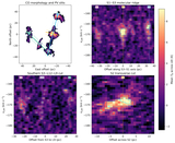
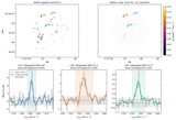
Caption: Figure 4.
Left: NOEMA CO(1–0) integrated intensity with HST Hα contours (cyan). The yellow rectangle marks the region enlarged in the right panel. The cross marks the adopted M33 center, and the curved yellow arrow shows the projected clockwise disk rotation (E. W. Koch et al. 2018). The semitransparent blue dashed curve is a schematic inner-arm guide through the southeastern multitracer ridge, not a fitted or previously cataloged spiral-arm locus. Right: enlarged view of the SE filament. Colors show CO(1–0), green contours show Hα, and blue circles mark young OB candidates from PHATTER (B. F. Williams et al. 2021). Circle size scales with F475W brightness. The curved yellow arrow indicates the projected disk rotation, the blue dashed outline marks the filament corridor used in the analysis, and the short gray dashed lines show the accepted transverse cuts. The three bright knots S1–S3 are marked with crosses. L9, L12, and L16 label neighboring SoFiA structures; L12 and L9 are discussed in Appendix B, while L16 is excluded based on its distinct morphology.
Other Images in This Article
Copyright and Terms & Conditions
© 2026. The Author(s). Published by the American Astronomical Society.

