Image Details
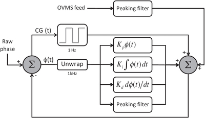
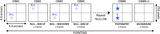
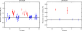
Caption: Figure 5.
Block diagram of LBTI OPD controller. The measured phase is first unwrapped and then goes through a classical PID controller. A peaking filter is also used to improve the rejection of specific vibration frequencies. An outer loop running at typically 1 Hz is used to monitor the group delay and capture occasional fringe jumps. In addition, real-time OPD variations induced by the LBT structure are measured by accelerometers all over the telescope (OVMS system) and feed-forwarded to the FPC. Differential tip/tilt is controlled following the same principle, except for the unwrapper and the outer loop.
Other Images in This Article

Show More
Copyright and Terms & Conditions
© 2016. The American Astronomical Society. All rights reserved.
Copyright ©
2025 Astronomy Image Explorer. All Rights Reserved.