Image Details
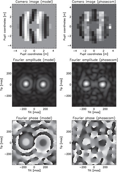
Caption: Figure 4.
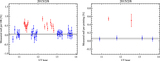
LBTI's phase sensing approach (noise-free model on the left and on-sky K-band data from 2014 March 17 on the right). Pupil images of the two interferometric outputs are formed on PHASECam (one output shown on top), and the Fourier transform is computed to sense both tip/tilt and phase. The peak position in the amplitude of the Fourier image (middle images) provides the differential tip/tilt error signal, while the argument of the Fourier image (bottom images) at the peak position provides the phase (gray scale ranging from −π to π). The central region of the pupil is excluded from the FFT (location of the secondary mirrors). Note that the camera image is padded in order to increase the resolution in the Fourier space.
Other Images in This Article

Show More
Copyright and Terms & Conditions
© 2016. The American Astronomical Society. All rights reserved.