Image Details
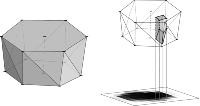
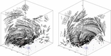
Caption: Figure 12.
Left panel: a schematic drawing of a "slice" volume along a flux tube, enclosed between two planes normal to the axis of the tube. A cross section of a flux tube is assumed to be a hexagon (not regular in general). Field lines are traced from the corners of the base cross section (a regular hexagon) and from the center of the base. For a given point along the axis field line (dashed line), a cross section is set by the intersection of the plane normal to the axis with the "corner" field lines. Right panel: the contribution of a given slice to the rendered image intensity at a given pixel is calculated as the volume of the portion of the slice that projects into the given pixel times the intensity multiplier of the slice (e.g., an emission measure). This quantity is equivalent to the line-of-sight depth of the feature times its filling factor.
Other Images in This Article

Show More
Copyright and Terms & Conditions
© 2013. The American Astronomical Society. All rights reserved.