

Image Details
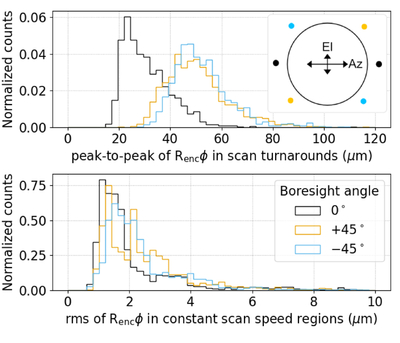
Caption: Figure 10.
Normalized histogram of the vibration-induced displacement of the SAT1 rotor, perpendicular to the line connecting the two encoders, during different phases of the constant elevation scans, quantified as Rencϕi (Section 2.2.2). Top panel: peak-to-peak rotor displacement at the scan turnarounds. The measured vibration-induced displacement is larger when the boresight angle is nonzero. Top right panel: schematic diagram of the encoder head locations relative to the rotor at boresight angles of 0° and ±45°. The encoder heads and rotor are indicated by small circles and a large black circle, respectively. The displacement is larger in the azimuth (scan) direction regardless of the boresight angle. When the boresight angle is zero, ϕi is only sensitive to the displacement in the elevation direction, whereas at ±45°, ϕi is equally sensitive to displacements in both azimuth and elevation directions, resulting in larger measured displacements. Bottom panel: rms of vibration-induced displacement in constant scan speed regions.
Other Images in This Article
Show More
Copyright and Terms & Conditions
© 2026. The Author(s). Published by the American Astronomical Society.

