

Image Details
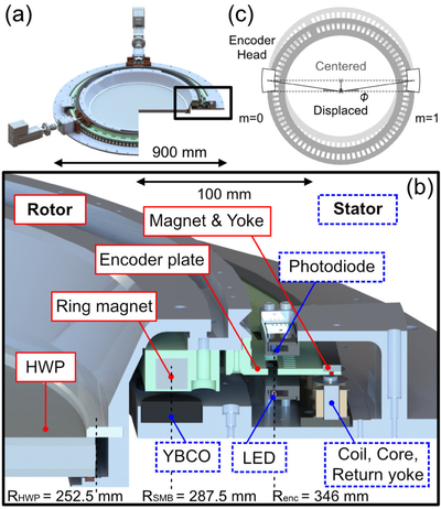
Caption: Figure 1.
HWP polarization modulator. (a) Computer-aided design (CAD) view of the whole system. (b) Magnified cross-sectional view of the rotation mechanism. The rotating components are labeled with red boxes, and the stationary components are labeled with blue dotted boxes. (c) Schematic view of the rotor and encoder heads when the boresight angle of the telescope is zero. When the rotor is off-centered perpendicular to the line connecting the encoders, the encoder incorrectly measures the rotation angle by ϕ.
Other Images in This Article
Show More
Copyright and Terms & Conditions
© 2026. The Author(s). Published by the American Astronomical Society.

Copyright ©
2026 Astronomy Image Explorer. All Rights Reserved.
