Image Details
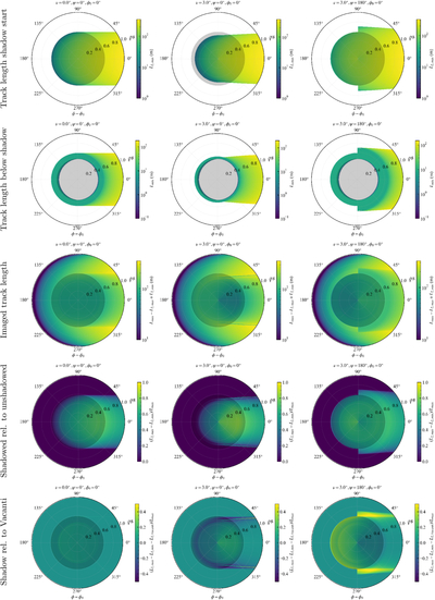
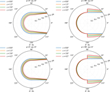
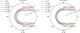
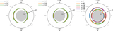
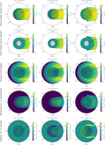
Caption: Figure 9.
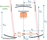
Shadow parameters shown for muons with different normalized impact distances ρR and impact angles ϕ0, for the parameters of an SCT. In the left panels, the muon is not inclined, in the center, it is inclined toward the left (ψ = 0°), and in the right panels, it is inclined to the right (ψ = 180°), with a fixed inclination angle ν = 3°. Note that the azimuthal axis represents the photon emission angle ϕ − ϕ0; see also Figure 5 for further details. From top to bottom, the panels show the maximum shadow distance, ﹩{L}_{2,{\rm{\max }}}﹩; the minimum shadow distance, ﹩{L}_{2,{\rm{\min }}}﹩; the total imaged muon track length, ﹩{L}_{{\rm{\max }}}-{L}_{2,{\rm{\max }}}+{L}_{2,{\rm{\min }}}﹩; the relative shadow contribution with respect to the unshadowed case; and the relative shadow contribution compared with the simplified case of a hole of radius Rsb using Vacanti’s formula. The gray shaded region in the center indicates the central hole in the primary mirror.
Other Images in This Article
Copyright and Terms & Conditions
© 2026. The Author(s). Published by the American Astronomical Society.