Image Details

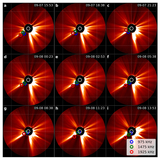
Caption: Figure 2.
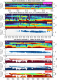
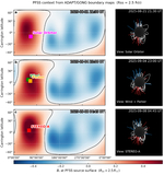
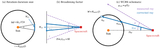
WCRS localization and observing geometry. (a) Polar view with spacecraft positions (red filled square: STEREO-A; green: Wind/Earth; orange: Parker Solar Probe; purple: Solar Orbiter); the radial coordinate is logarithmic. Colored wedges indicate the propagation directions and full angular widths of three fast CMEs, with onset times and sheath (shock-front) speeds from the NASA/CCMC DONKI CME catalog (coronagraph-based fits from available viewpoints). We use these catalog fits for timing/geometry context only; uncertainties are larger for the farside CME1, and we do not attempt a detailed CME reconstruction. (b)–(d) WCRS source trajectories (close-side ray-sphere solutions) for 975, 1475, and 1925 kHz, projected onto the HEEQ equatorial (x–y) plane and color coded by time during Window 3. (e) Spacecraft heliolongitudes vs. time; horizontal bars mark the three type IV visibility windows.
Other Images in This Article
Copyright and Terms & Conditions
© 2026. The Author(s). Published by the American Astronomical Society.