Image Details
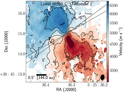
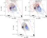
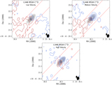
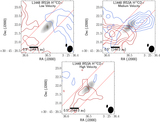
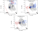
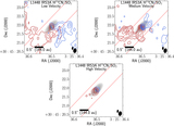
Caption: Figure 6.
C17O velocity-weighted integrated intensity maps toward IRS3B and IRS3A over a selected range of velocities (1.27 ﹩\to ﹩ 7.65 km s−1) The C17O emission appears well ordered across the semimajor axis. The contours denote the 0.5 km s−1 velocity offsets from system velocity of 4.8 km s−1. The yellow markers indicate the three continuum sources. The black lines indicate the position angle of the minor disk estimates as given by the pdspy fitting routine in Table 4, of ﹩90+{26.7}_{-2.9}^{+1.8}﹩°. The C17O synthesized beam (0.″21 × 0.″13) is the bottom rightmost ellipse.
Other Images in This Article

Show More
Copyright and Terms & Conditions
© 2021. The American Astronomical Society. All rights reserved.
Copyright ©
2026 Astronomy Image Explorer. All Rights Reserved.