Image Details

Caption: Figure 1.
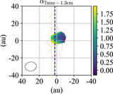
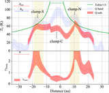
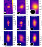
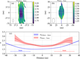
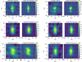
(a)–(c) Intensity maps for the observed data at ALMA Band 7, and JVLA Q- and K-bands, respectively. The color map represents the brightness temperature. The horizontal and vertical axes indicate west–east and south–north directions. The white ellipses at the bottom left indicate the beam sizes (θmaj × θmin; P.A.): 0.″072 × 0.″067; −11° (Band 7), 0.″087 × 0.″068; 76° (Q band), and 0.″095 × 0.″075; −82° (K band). The rms noise level is 0.3 K, 11 K, and 21 K for Band 7, Q band, and K band, respectively. In the ALMA Band 7 image, the green contours show the brightness temperature; the first contour starts at 10σ, and the interval is 23σ. The clump locations are marked with the crosses. For the JVLA images, the green contours show the brightness temperature observed at Q band; the first contour is at 3.5σ (∼40 K), and the interval is 3.0σ. (d) the bottom right panel shows the Q band image where free–free contamination is subtracted. The beam size is 0.″096 × 0.″076; −82°. The solid blue contours in the subtracted map are plotted in the same manner as (b) and (c), but with 1.5σ intervals and the rms noise level in the smoothed Q band data, σ′ ∼ 7 K. The estimated free–free emission for Q band is indicated by the green dashed contours at 2, 3, 4, and 5σ′. The blue dashed line indicates the midplane, which we define as the north–south line passing through the peak position of clump-N in the subtracted image.
Copyright and Terms & Conditions
© 2020. The American Astronomical Society. All rights reserved.


