Image Details
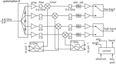
Caption: Figure 6.
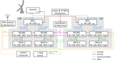
Simplified schematic diagram of the BDC. Only one of the two (identical) polarization channels is shown, and several intermediate amplification stages are omitted. Two local oscillators maser-locked and tuned to 6 GHz and 7 GHz are used to mix all the filtered IF bands between 4 and 9 GHz to baseband (0–2 GHz). For 230 GHz operation, a 5–9 GHz IF band is split with output of 5–7 GHz (“low-band”) and 7–9 GHz (“high-band”). For 345 GHz operation, a 4–8 GHz IF band is split with an output of 4–6 GHz (“low-band”) and 6–8 GHz (“high-band”). The 6 and 7 GHz local oscillator signals are also sent to the other polarization channel. The attenuation and band selection can be set using a control panel or remotely via an Ethernet connection.
Other Images in This Article
Show More
Copyright and Terms & Conditions
© 2019. The American Astronomical Society.