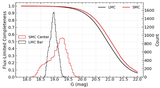
Image Details
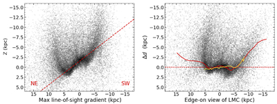
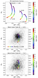
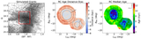
Caption: Figure 13.
Edge-on view of the LMC disk structure. Left: the 3D distribution of LMC RC stars projected along the axis of maximum LOS depth gradient (i.e., perpendicular to the LON), plotted against the vertical coordinate z (in kiloparsecs). The inclination of the LMC disk causes the northeastern side to be closer and the southwestern side farther away. The red dashed line shows our inner best-fit plane to the disk, capturing its global tilt. Right: the same edge-on projection after correcting for the disk’s inclination. The vertical axis shows the residual distance Δd from the best-fit plane. The red curve traces the median residual distance, weighted by the local on-sky stellar density. The yellow curve shows the median profile from Y. Choi et al. (2018a), overplotted for comparison.
Other Images in This Article
Show More
Copyright and Terms & Conditions
© 2026. The Author(s). Published by the American Astronomical Society.