Image Details
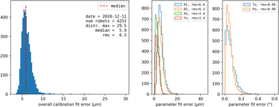
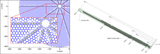
Caption: Figure 8.
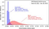
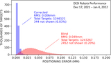
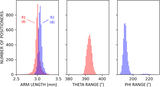
Best-fit errors for a calibration measurement of 4252 positioner robots, performed in 2020 December. For each positioner, transformation parameters between (θ, ϕ) and (x, y) coordinates were calculated so as to minimize the error between measured and predicted fiber locations. The minimization in this case was done on a data set of 62 points per robot. The left plot shows the distribution of the transformation’s overall fit error for each unit (6.5 μm rms). The middle and right plots show errors on the six key kinematic parameters independently. “R1” and “R2” are respectively the kinematic arm lengths between central (θ) and eccentric (ϕ) axes, and between the eccentric axis and fiber. “Xo” and “Yo” are the location of the central axis on the focal plane. “To” and “Po” are angular zero-points for the θ and ϕ axes, respectively. The Xo and Yo fit errors are effectively a measure of FVC measurement precision.
Other Images in This Article
Show More
Copyright and Terms & Conditions
© 2022. The Author(s). Published by the American Astronomical Society.