Image Details
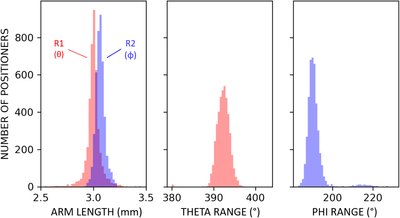
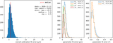
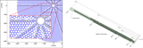
Caption: Figure 7.
Distributions for several key calibration parameters for the fiber positioner robots. At left are the kinematic arm lengths of the two robot axes. “R1” is the distance from the θ rotation axis to the ϕ rotation axis. “R2” is the distance from the ϕ axis to the fiber. The maximum radius to which a given robot unit can move its fiber is its particular value for (R1 + R2). At the center of each unit there is an inaccessible zone of radius ∣R1 − R2∣. The middle and right plots show the maximum travel ranges from hardstop-to-hardstop for the θ and ϕ axes, respectively. The ϕ range distribution is bimodal due to a period of several months during robot production where ϕ bearings were being glued at a spacing ∼0.5 mm further than nominal off their housings, thus increasing the effective travel range. Other calibration parameters (not shown here) include the center position of the θ rotation axis, angular zero-points of θ and ϕ, and effective gear output ratio for each axis (equal to 1.0 for nominally functioning robots).
Other Images in This Article
Show More
Copyright and Terms & Conditions
© 2022. The Author(s). Published by the American Astronomical Society.