Image Details
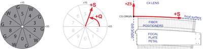
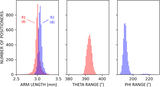
Caption: Figure 10.
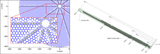
Left: we selected the pattern of guider versus wave front cameras (indicated by “G” and “W”) to maximize spacing of the wave front measurements, since they must control the tip/tilt degrees of freedom of the hexapod. Middle and right: at the interfaces between software systems—such as move scheduling (Section 3.3) and PlateMaker (Section 3.5)—we use a modified polar coordinate system (Q, S), where “S” is the distance along the aspheric focal surface within a plane that intersects the optical axis and is at angle “Q” with respect to the cartesian coordinates of the focal plane (X5, Y5, Z5). By matching the natural geometry of the focal surface, the coordinate system removed several possible sources of ambiguity between developers.
Other Images in This Article
Show More
Copyright and Terms & Conditions
© 2022. The Author(s). Published by the American Astronomical Society.