

Image Details
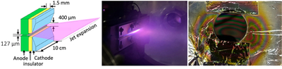
Caption: Figure 1.
(Left) Schematic of the PDN (adapted from B. H. P. Broks et al. 2005). (Center) Picture of the pulsed plasma planar expansion through the slit. (Right) Picture of the tholin sample deposited on a silicon substrate. Iridescent features resulting from the optical interference with the thin-film deposition can be seen.
Other Images in This Article
Copyright and Terms & Conditions
© 2026. The Author(s). Published by the American Astronomical Society.

Copyright ©
2026 Astronomy Image Explorer. All Rights Reserved.
