

Image Details
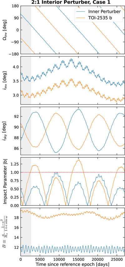
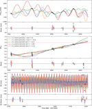
Caption: Figure D1.
Variation in orbital elements for the “2:1, interior perturber case 1” solution. The top two panels show the longitude of ascending node and inclination, measured with respect to the system invariable plane. The third panel shows the inclination with respect to the sky plane, while the fourth panel shows the unsigned impact parameter. The fifth panel shows the variation in ﹩B\equiv \frac{a}{{R}_{\star }}\frac{1-{e}^{2}}{1+e\sin \omega }﹩. The gray shaded region corresponds to the time spanned by the observed data and plotted in Figure 5.
Other Images in This Article
Copyright and Terms & Conditions
© 2026. The Author(s). Published by the American Astronomical Society.

Copyright ©
2026 Astronomy Image Explorer. All Rights Reserved.
