Image Details
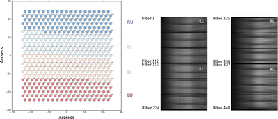
Caption: Figure 4.
The layout of the fibers associated with each IFU. The left-hand panel displays the nominal fiber arrangement in the focal plane and their corresponding detectors and amplifiers. The fibers are numbered 1 to 448. This image represents the standard alignment, though there are a handful of IFUs with different layouts. The right-hand panel shows the layout of the spectra from the fibers on the detectors. The horizontal is the wavelength direction, and the vertical is the fiber direction. Each spectrograph is split into two sides, each with its own detector, “L” and “R”, and each detector (or side) has two amplifiers, designated “U” and “L”.
Other Images in This Article
Show More
Copyright and Terms & Conditions
© 2021. The Author(s). Published by the American Astronomical Society.