Image Details
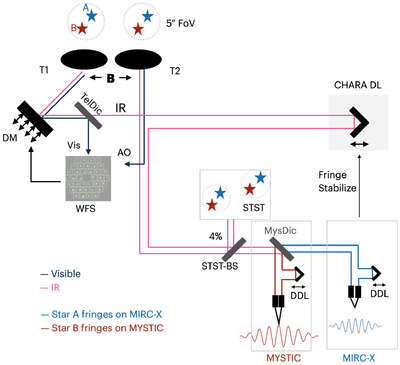
Caption: Figure 4.
Schematic optical layout of the CHARA dual-field mode. For clarity, we show only two telescopes and suppress the second-telescope AO/CHARA delay-line path. The ∼5″ field is acquired at the telescopes; visible light feeds the AO/Wavefront Sensor via the telescope dichroic (TelDic), while the IR beam is relayed to the beam-combiner lab and main CHARA delay lines. The full field is imaged by STST, then a small pickoff (STST-BS) sends light to MIRC-X (H band) and MYSTIC (K band). MIRC-X fringe-tracks on component A and drives the main delay lines; MYSTIC records science fringes on component B (see Figure 5). The instrument DDLs apply the additional differential delay B · θ between A and B, shifting the science beam relative to the fringe-tracking path. The fiber injection is set from the STST astrometric positions. Unlike VLTI/GRAVITY, CHARA does not have an internal metrology system; differential delays are inferred from DDL telemetry and A–B/B–A swap tests. This schematic illustrates the functional architecture rather than the full optical complexity of the six-telescope CHARA beam train.
Other Images in This Article
Copyright and Terms & Conditions
© 2026. The Author(s). Published by the American Astronomical Society.