Image Details
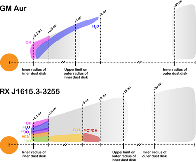
Caption: Figure 10.
Schematics of the disks of GM Aur (top panel) and J1615 (bottom panel). In the bottom panel, the order of the species from disk surface to midplane follows with increasing best-fit temperatures in Table 3. The right-hand edge of each colored region for each species correlates with the approximate location of the best-fit emitting radius described in Section 3.1 and Table 3. Note that the emitting radius may correspond to a full disk of emission with R or a ring with an area equal to πR2. The gray shaded areas represent disk radii where dust is present. The base of the disk cross section extends only to the midplane. For GM Aur, the inner dust disk has been observed to extend up to 3.2 au (L. Francis & N. van der Marel 2020) and up to 15 au in J1615 (A. Sierra et al. 2024). The inner radius of the inner dust disks in both targets corresponds to the inner radius modeled in Section 3.2.
Other Images in This Article
Show More
Copyright and Terms & Conditions
© 2025. The Author(s). Published by the American Astronomical Society.