Image Details
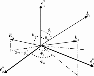
Caption: Fig. 3.
Left: Coordinate system used to describe scattering in the electron rest frame. The polar axis, ﹩\boldsymbol{e}^{*}_{z}﹩, is chosen to coincide with direction of the electron motion in the observer frame. The definitions of ﹩\boldsymbol{e}^{*}_{x}﹩ and ﹩\boldsymbol{e}^{*}_{z}﹩ are seen in eq. (A2). The vectors ﹩\boldsymbol{k}_{0}﹩ and ﹩\boldsymbol{k}_{1}﹩ are the directions of the background and the scattered radiation, respectively. If the background radiation is polarized, the vector ﹩\boldsymbol{E}_{w}﹩ is used to represent its polarization plane. Right: Coordinate system on the sky; ﹩\Omega _{p}﹩ and ﹩\boldsymbol{e}^{*}_{\mathrm{zp}\,}﹩ are, respectively, the directions of the rotational axis and of the particle motion projected on the sky. The position angle of the polarization plane (﹩\boldsymbol{E}_{\mathrm{sw}\,}﹩) is measured counterclockwise from the direction of the rotational axis on the sky.
Other Images in This Article
Show More
Copyright and Terms & Conditions
© 2007. The American Astronomical Society. All rights reserved. Printed in U.S.A.