Image Details

Caption: Fig. 7.
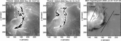
Left and middle: TRACE 1600 Å images of the X2.3 flare at ﹩t_{1}=15\thinspace{:}\thinspace 07\thinspace{:}\thinspace 34﹩ and ﹩t_{2}=15\thinspace{:}\thinspace 14\thinspace{:}\thinspace 21﹩. The dashed lines indicate the outer edge of the flare ribbons at each time. Right: MDI magnetogram of the same field of view. The dashed lines indicate the locations of the outer edges of the ribbons both at ﹩t=t_{1}﹩ and t2. The solid lines in the left panel indicate the length of the ribbon Lribbon for the east (left) and west (right) ribbons.
Copyright and Terms & Conditions
© 2005. The American Astronomical Society. All rights reserved. Printed in U.S.A.


