Image Details
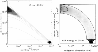
Caption: Fig. 5.
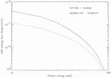
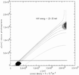
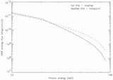
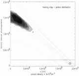
Calculated loop intensity maps; comparison of the looptop sources obtained with the two‐field models. Note that in the right‐hand panel, taken from Fletcher (1995), the photon energy given in fact refers to the upper energy of a 10 keV wide bin; i.e., this is the integrated emission in the 20–30 keV bin. Note that the gray scale is not consistent between the two images, but the plotted contours are, allowing comparison of the source sizes. All contours are relative to the highest counts in the image and are plotted at 12.5%, 17.5%, 25% , 34%, 50%, and 70%.
Copyright and Terms & Conditions
© 1998. The American Astronomical Society. All rights reserved. Printed in U.S.A.


