Image Details
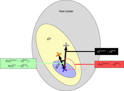
Caption: Figure 3.
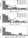
Schematic alignment between BCG (blue), ICL (yellow), and host cluster (gray). All three components have different position angles (PA), which are measured independently from the offset direction. The two black arrows point from the BCG center toward the ICL center or host-cluster center, each marked with a cross. The angle θ of these vectors is counted counterclockwise from the horizontal, red dashed line. However, only the absolute difference (green) between the two angles is of interest because it is the offset direction of the ICL with respect to the BCG. If the ICL is offset toward the host cluster center, then ﹩| \theta ({{\boldsymbol{r}}}_{0}^{\mathrm{Cluster}}-{{\boldsymbol{r}}}_{0}^{\mathrm{BCG}})-\theta ({{\boldsymbol{r}}}_{0}^{\mathrm{ICL}}-{{\boldsymbol{r}}}_{0}^{\mathrm{BCG}})| =0^\circ ﹩.
Other Images in This Article

Show More
Copyright and Terms & Conditions
© 2021. The American Astronomical Society. All rights reserved.