

Image Details
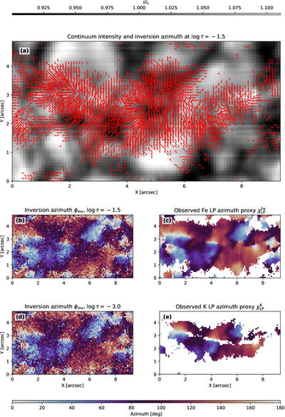
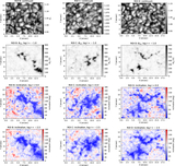
Caption: Figure 2.
Transverse magnetic field structure of the network element in the region highlighted by the dashed red box in Figure 1. (a) The background shows the continuum intensity, while the red line segments indicate the corresponding magnetic azimuth, with lengths proportional to B⊥. (b) Magnetic azimuth ϕinv inferred from the inversion at ﹩\mathrm{log}\tau =-1.5﹩. (c) Azimuth proxy χLP derived directly from the observed linear polarization of the Fe I 8468 Å line. Panels (d) and (e) show the same as (b) and (c) but for ﹩\mathrm{log}\tau =-3.0﹩ and the K I 7699 Å line. In the lower panels (b)-(e), pixels are masked unless the amplitude of either Stokes Q or U exceeds 5σQU at one or more wavelengths. The close correspondence between the inversion and the proxy shows that the lateral variation in field orientation is already present in the observed Stokes profiles.
Other Images in This Article
Copyright and Terms & Conditions
© 2026. The Author(s). Published by the American Astronomical Society.

