Image Details
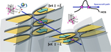
Caption: Figure 4.
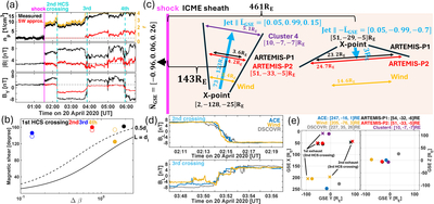
Approximated preshock solar wind conditions, magnetic shear versus Δβ across the HCS crossings, and a sketch of the HCS reconnection exhausts downstream of an interplanetary shock in the ICME sheath. Panel (a) shows the approximated preshock solar wind conditions based on the magnetohydrodynamic Rankine–Hugoniot relations (yellow), with the compression ratio r given by the ratio of proton density in the sheath and upstream of the shock. The dashed horizontal lines represent the reference values measured upstream of the shock. Panel (b) shows magnetic shear and Δβ across the HCS crossings, with open circles denoting the magnetic shear in the approximated preshocked solar wind. The theoretical curves are shown for pressure gradient layer widths of L = 0.5 di and L = 1.0 di. Panel (c) illustrates the exhaust directions, widths, X-point locations and exhaust distances from the shock at 1 au as well as the exhaust geometries. The “Jet ﹩| | \pm \bar{{L}}﹩” labels refer to an exhaust jet in the ±L direction. Panel (d) shows the BL profiles across the exhausts as observed by the L1 fleet. The ACE and DSCOVR data are time shifted to align with the Wind data. Panel (e) shows the spacecraft positions in GSE coordinates and the X-point locations from single spacecraft measurements based on a fast reconnection rate of 0.1.
Other Images in This Article
Copyright and Terms & Conditions
© 2025. The Author(s). Published by the American Astronomical Society.