Image Details
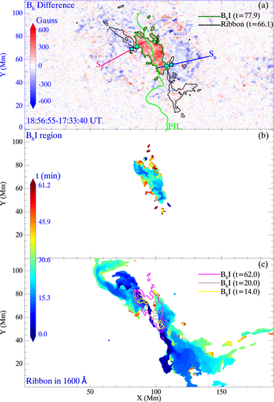
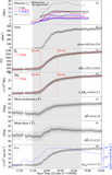
Caption: Figure 1.
Evolution of B h increase (abbreviated as “B h I” in figures) in case 33. (a) A postflare B h difference image. The black-green contours outline the postflare mask of the B h increase (pixel value ≥ 120 G); the black contours outline the flare ribbons at one moment for comparison. “t” (in minutes) indicates time after flare start (GOES start time). S p and S n are slices in positive and negative polarities used to determine the representative points of the region fronts (cyan squares). (b)–(c) Spatiotemporal evolution masks for the B h increase and flare ribbons, color-coded by the time elapsed from flare start. Colored contours in (c) outline B h -increase regions at different times. The associated animation lasts from 2017-09-06T17:38 to 2017-09-06T18:56, showing the B h increase and ribbon evolution. Its frames have a similar layout to the figure.
(An animation of this figure is available.)
The video/animation of this figure is available in the online journal.
Copyright and Terms & Conditions
© 2022. The Author(s). Published by the American Astronomical Society.


