

Image Details
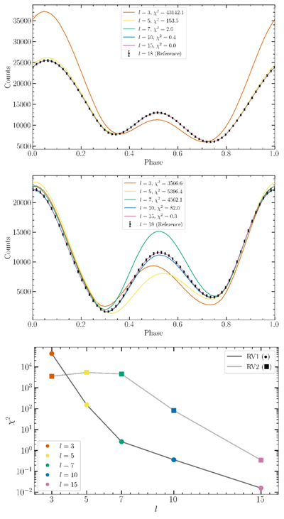
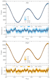
Caption: Figure 12.
Top and middle panels: model light curves for the RV1 and RV2 input field configurations, respectively, at truncation orders l ∈ {3, 5, 7, 10, 15} (colored lines), overlaid on the l = 18 reference (black points with NICER-like uncertainties). The χ2 values with respect to the reference light curve are indicated in the legend. (We note that these light curves would recover the exact RV1 and RV2 light curves of CK21 if the swept-back Bout were replaced by the corresponding static-vacuum configuration). Bottom panel: χ2 as a function of multipolar truncation order l for the above cases: RV1 (circles, black connecting line) and RV2 (squares, gray connecting line). Colors indicate the truncation order l, as shown in the legend.
Other Images in This Article
Show More
Copyright and Terms & Conditions
© 2026. The Author(s). Published by the American Astronomical Society.

