Image Details
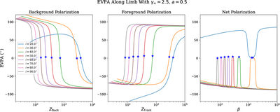
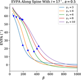
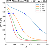
Caption: Figure 10.
Limb polarization angle as a function of inclination, plotted for ϕ − ϕTL = 1°, where ϕ is the background azimuthal coordinate of the emission and ϕTL is the azimuthal coordinate of the TL (see Section 4.2.2 for more details). The individual panels represent the background emission (left), foreground emission (middle), and net sum (right). In all three cases, the predicted location of ﹩{\tilde{R}}_{{\rm{limb}}}﹩ (Equation (49), the location at which fR = 0) is marked as a blue star. Unlike the spine (Figure 6), only a single blue star is needed here because the foreground and background coincide at the limb. The polarization angle swings rapidly around ﹩{\tilde{R}}_{{\rm{limb}}}﹩ in all cases. Note that we have plotted only one of the two limbs here: the receding limb for i = 20° and the approaching limb for all other inclinations (see Equation (41)).
Other Images in This Article
Show More
Copyright and Terms & Conditions
© 2026. The Author(s). Published by the American Astronomical Society.