Image Details
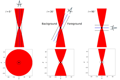
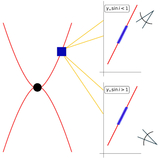
Caption: Figure 1.
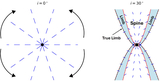
Three different viewing geometries (i = 0°, i = 30°, and i = 90°) for a sample jet, with coordinate axes plotted in units of M. For each inclination angle, the position of the observer is shown on top, with the corresponding projected image shown below. The filled-in black circle corresponds to the black hole, and the black dashed line demarcates an impact parameter of b = 7 M. The solid blue line demarcates the origin of the observer’s screen. In practice, the i = 90° case is typically not observable due to lack of Doppler boosting, but it is conceptually useful.
Other Images in This Article
Show More
Copyright and Terms & Conditions
© 2026. The Author(s). Published by the American Astronomical Society.
Copyright ©
2026 Astronomy Image Explorer. All Rights Reserved.