Image Details

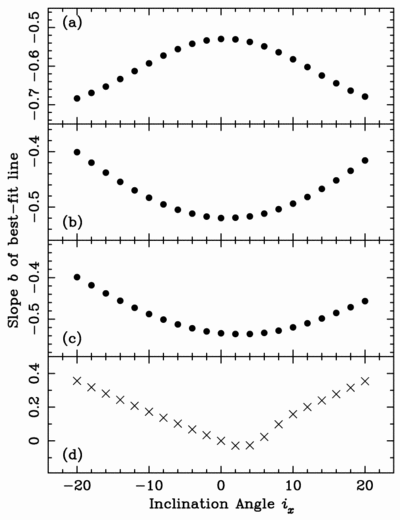
Caption: Fig. 23.
Data similar to Fig. 21 but for a simulated frustum, oriented as in Fig. 22, with its axis along line A, and inclinations ﹩i_{x}﹩ made in the plane V. Panels (a)–(c) use a frustum with large opening angle, simulating the shell echoes. Best‐fit slopes are calculated as follows: (a) Points sampling the complete surface of revolution. (b) Points within 30° of plane H. (c) Points from 30° below to 60° above plane H, meant to simulate the positions of actual shell echoes. (d) Points along the upper half of a frustum with small opening angle, simulating the jet material.
Copyright and Terms & Conditions
© 2005. The American Astronomical Society. All rights reserved. Printed in U.S.A.


