Image Details
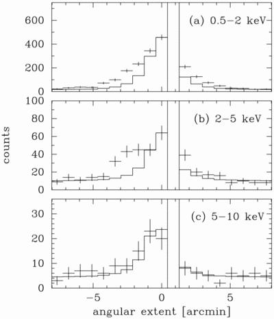
Caption: Fig. 2.
Brightness profile projected onto the detector x‐axis in (a) 0.5–2 keV, (b) 2–5 keV, and (c) 5–10 keV. The crosses are SIS0 data, and the histogram represents the PSFs of XRT + SIS added on the background level. The region at an angle of ~1﹩\arcmin﹩ corresponds to the interchip gap of the SIS detector.
Copyright and Terms & Conditions
© 1998. The American Astronomical Society. All rights reserved. Printed in U.S.A.


