

Image Details
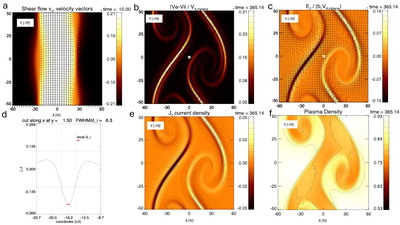
Caption: Figure 2.
Current sheets a few ion inertial lengths (di) wide generated by an MHD-scale KH vortex in a 2.5D Hall–MHD simulation at the low-corona parameters of Table 2 (model and parameters in Appendix B). Lengths are in units of L0 = 2 di and times in units of L0/VA0; the horizontal axis (x) is the direction normal (N) to the flux channel and the vertical axis (y) the flow direction (−M). (a) Initial state (t = 10): flow speed vy (color) with velocity vectors; the channel at rest between x = ± 25 is sheared on both flanks by exterior flow at 0.33 VA0 (the color scale saturates at 0.21 VA0), and the in-plane field component reverses at each flank over a half-width of 16 di, so the initial state contains no kinetic-scale structure. (b) Relative electron–ion flow ∣ve − vi∣ at t = 365, normalized to the Alfvén speed of the far-field in-plane field component, with in-plane field lines. The decoupling is confined to the thin braid sheet between the two vortices and to the flank sheet, where it exceeds 0.3 (the color scale saturates); the vortex interiors show none. (c) Parallel electric field E∥ = η J · B/∣B∣, normalized to b∥VA,in of the far field, with in-plane field lines and in-plane magnetic-field vectors; with uniform resistivity it follows the current sheets. (d) jz along a cut across the braid sheet at y = 1.5: the FWHM (dashed lines) is 6.3 di along the cut and about 4 di perpendicular to the sheet, which is inclined by 39∘ to the cut, while the core of the trough, where the current density is highest, is only 1–2 di wide. The short bar marks the local ion inertial length; the weaker layers of opposite polarity on either side are 9 di away. (e) Current density jz at t = 365: the braid and flank sheets, with weaker layers of alternating polarity wound into both vortices. (f) Plasma density at t = 365: the channel plasma (0.9 n0, orange) wound into both vortices by the exterior plasma (1.1 n0, white).
Other Images in This Article
Copyright and Terms & Conditions
© 2026. The Author(s). Published by the American Astronomical Society.

