Image Details
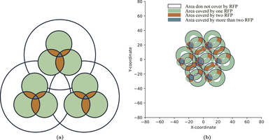
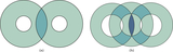
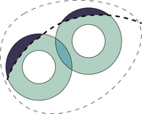
Caption: Figure 13.
(a) Schematic diagram of a new-generation RFP insertion into a large positioner hole with partial coverage. The two colors (blue and orange) represent the conflict areas. The outer circle represents the pre-existing range of motion of the RFP. (b) This figure presents the optimized result of using new-generation RFPs to replace the original RFPs for full coverage (for a clearer view, only seven RFPs are shown).
Other Images in This Article
Show More
Copyright and Terms & Conditions
© 2026. The Author(s). Published by the American Astronomical Society.
Copyright ©
2026 Astronomy Image Explorer. All Rights Reserved.