Image Details
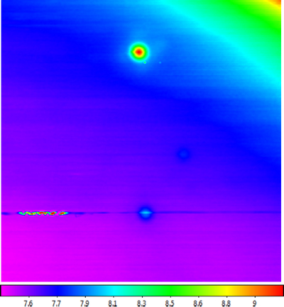
Caption: Figure 5.
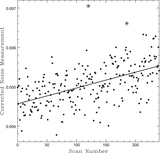
Raw map of Virgo A (top), 3C 270 (center right), and 3C 273 (bottom), acquired with the 20 m in the L-band, using a 1/10 beamwidth horizontal raster. Left and right linear polarization channels have been summed, partially symmetrizing the beam pattern (Figure 3). A locally modeled surface (Section 1.2.1, see Section 3.7) has been applied for visualization only. All three signal contaminants are demonstrated: (1) en-route drift, the low-level variations along the horizontal scans, (2) RFI, both long duration, during the scan that passes through 3C 273, and short duration, near Virgo A, and (3) elevation-dependent signal, toward the upper right, which was only ≈11° above the horizon.
Other Images in This Article

Show More
Copyright and Terms & Conditions
© 2019. The American Astronomical Society. All rights reserved.