Image Details
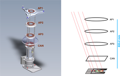
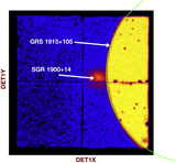
Caption: Figure 1.
Schematic of the path of stray light photons. (Left) CAD rendering of the focal plane and aperture stop assembly. (Right) Red lines show the stray light paths that survive to the focal plane after passing around the aperture stop (AP1, AP2, and AP3) rings and the “can” housing the detectors. The height offset from the focal plane to AP1 is shown on the right. Figures adapted from Madsen et al. (2017a).
Other Images in This Article
Show More
Copyright and Terms & Conditions
© 2021. The American Astronomical Society. All rights reserved.
Copyright ©
2025 Astronomy Image Explorer. All Rights Reserved.