Image Details

Caption: Fig. 1.
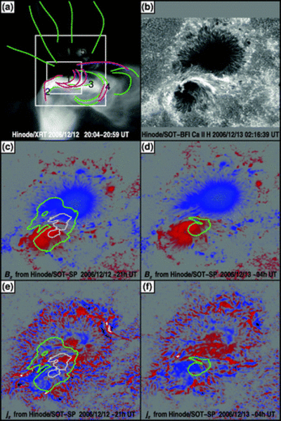
Chromosphere, corona, and magnetic field of NOAA AR 10930. (a) The ﹩320\times 320﹩ pixel footprint of the full model volume for the NLFFF codes (itself surrounded by a much larger skirt of a line‐of‐sight magnetic map). The largest square is the ﹩224\times 224﹩ pixel area (with sides of 101 Mm) used for the energy estimates and is shown in (b–d) and in Figs. 3 and 4. The smaller square shows the footprint shown in Fig. 2. (a) Time‐averaged Hinode/XRT soft X‐ray image. Individual loops traced on this image or on a TRACE 195 Å image (not shown here) are represented in green; the best‐matching model field lines for the ﹩\mathrm{Wh}\,^{+}_{\mathrm{pp}\,}﹩ model field are shown in purple. Numbers identify the characteristic signatures in the field that were used in the subjective assessment of the goodness of fit, as discussed in § 3. (b) Chromospheric Ca II H image for the onset phase of the flare. (c) Preflare Hinode/SOT SP ﹩B_{z}﹩ on 2006 Dec. 12 around 21 UT. Contours show the vertically integrated energy density in the ﹩\mathrm{Wh}\,^{+}_{\mathrm{pp}\,}﹩ field minus that of the potential field; the white contour lies near the maximum value and the green contour at half that. (d) Postflare Hinode/SOT SP ﹩B_{z}﹩ on 2006 Dec. 13 around 4 UT. Contours are as in (b). (e, f) Maps of the vertical current density ﹩j_{z}﹩ corresponding to the pre‐ and postflare maps shown in (c) and (d), respectively. The color scale for the bottom four panels runs from blue (negative) to red (positive), saturating into black or white, respectively.
Copyright and Terms & Conditions
© 2008. The American Astronomical Society. All rights reserved. Printed in U.S.A.


