Image Details
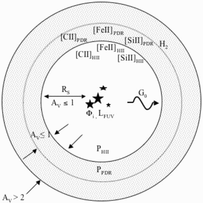
Caption: Fig. 16.
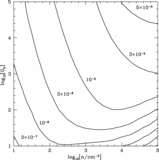
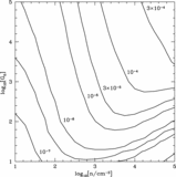
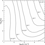
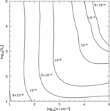
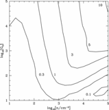
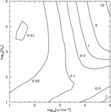
Schematic representation of the merged H II region and PDR models. ﹩P_{\mathrm{H}\,\,{}^{{\rm{\small II}}}}=P_{\mathrm{PDR}\,}﹩. Starburst99 is used for the cluster spectrum. Mappings is used for the H II region structure; emitted H II region spectrum; ﹩[ \mathrm{Fe}\,\ {}^{{\rm{\small II}}}] _{\mathrm{H}\,\,{}^{{\rm{\small II}}}}﹩, ﹩[ \mathrm{Si}\,\ {}^{{\rm{\small II}}}] _{\mathrm{H}\,\,{}^{{\rm{\small II}}}}﹩, and ﹩[ \mathrm{C}\,\ {}^{{\rm{\small II}}}] _{\mathrm{H}\,\,{}^{{\rm{\small II}}}}﹩ emission; and RS. The emitted spectrum plus RS gives G0. Our PDR models give [Fe II]PDR, [Si II]PDR, [C II]PDR, and H2 emission. AV in the H II region is ≲1, AV in the PDR is ![]() 2, and AV at the H I/H2 boundary is ≲1.
2, and AV at the H I/H2 boundary is ≲1.
Other Images in This Article
Show More
Copyright and Terms & Conditions
© 2006. The American Astronomical Society. All rights reserved. Printed in U.S.A.