Image Details
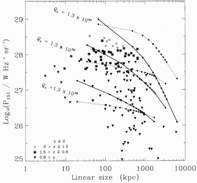
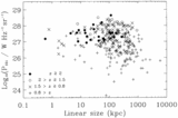
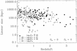
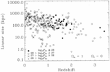
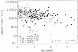
Caption: Fig. 13.
We overlay on this plot in solid lines the tracks through the P‐D plane of three sources (upper to lower) with Q0 = 1.3 × 1040 W at z = 2, Q0 = 1.3 × 1039 W at z = 0.5, Q0 = 1.3 × 1038 W at z = 0.2. We overlay in dotted lines the tracks from the model of Kaiser et al. (1997) for sources with the same jet powers and redshifts. The larger symbols in this plot show the rest‐frame luminosities at 151 MHz of members of the 3C complete sample (§ 3.1) against their projected linear sizes. Since this is a logarithmic plot, the differences in the distributions between the projected and the true linear sizes of sources will be slight. Small dots lie on the tracks to indicate the times 1, 10, 20, ... , 100, 200 Myr through the source's life. All tracks in this figure were generated assuming an environment as described in § 8.2, i.e., with β = 1.5 and with c1 = 1.8.
Copyright and Terms & Conditions
© 1999. The American Astronomical Society. All rights reserved. Printed in U.S.A.


