

Image Details
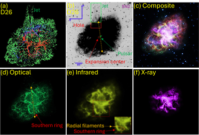
Caption: Figure 1.
Images of the Crab Nebula with the new identification of the southern ring as a counterstructure to the northern jet. (a) An image adapted from Z. Ding et al. (2026) presenting their three-dimensional reconstruction of the Crab Nebula in [O III] λλ4959, 5007 (green), Hβ (blue), and He I λ5876 (red). This image presents the northern jet structure as in Z. Ding et al. (2026). The jet was identified by S. van den Bergh (1970). (b) An optical figure adapted from Z. Ding et al. (2026). The green and red boxes indicating the northern jet region and the hole region, respectively, are from the original figure in Z. Ding et al. (2026). The circle at the center represents the expansion center determined by R. L. Nugent (1998), the “X” at the center is the location of the Crab pulsar (e.g., D. L. Kaplan et al. 2008), and the short arrow on the X indicates pulsar proper motion (C.-Y. Ng & R. W. Romani 2006); all are marks from Z. Ding et al. (2026). I added only the double-sided orange arrow, copied from panel (d). Panels (c)–(f) are from the Chandra Site (https://chandra.harvard.edu/photo/2017/crab/) (G. Dubner et al. 2017; Credits: X-ray: NASA/CXC/SAO; Optical: NASA/STScI; Infrared: NASA/JPL/Caltech; Radio: NSF/NRAO/VLA; Ultraviolet: ESA/XMM-Newton). They are all in the same scale as panel (b); panel (a) has a different scale. (c) A composite image: X-ray (Purple), Ultraviolet (Blue), Optical (Green), Infrared (Yellow–Green), and Radio (Red). (d) An optical image. I added the pulsar position and expansion center marks, identified the ring, and drew double-sided arrows to mark my proposed pair of jet axes (the arrow lengths have no meaning). (e) An infrared image where the inset shows the rings I identified. (f) An X-ray image to show that the pulsar-wind nebula is not correlated with the pair of jets.
Copyright and Terms & Conditions
© 2026. The Author(s). Published by the American Astronomical Society.

