Image Details

Caption: Fig. 4.
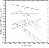
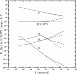
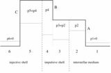
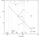
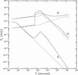
Example of the kinetic‐energy–dominated shell injection case. Parameters: for the impulsive shell 3, total energy ﹩E_{0,3}=10^{51}﹩ ergs and dimensionless entropy ﹩\gamma _{0,3}=300﹩; for the injective shell 6, ﹩E_{0,6}=5\times 10^{50}﹩ ergs and ﹩\gamma _{0,6}=500﹩. The central engine activity time for the rear shell is ﹩\delta T_{6}=100﹩ s; the time interval between ejecting the two shells is ﹩\Delta T_{36}=10﹩ s. ISM baryon number density ﹩n_{1}=1\,\mathrm{cm}\,^{-3}﹩; electron spectral index ﹩p=2.5﹩. Equipartition parameters ﹩\epsilon _{e}=0.1﹩ and ﹩\epsilon _{B}=0.02﹩. The source redshift ﹩z=1﹩. (a) Evolution of various Lorentz factors with blast‐wave radius R. The terms ﹩\gamma _{\mathrm{A}\,}﹩, ﹩\gamma _{\mathrm{B}\,}﹩, and ﹩\gamma _{\mathrm{C}\,}﹩ are the random Lorentz factors of the emission sites heated by shocks A, B, and C, respectively. The curves are solid when the shocks are on and are dotted when they are off. The terms ﹩\gamma _{3}﹩, ﹩\gamma _{4}﹩, and ﹩\gamma _{6}﹩ are the bulk Lorentz factors of the regions 2+3, 4+5, and 6, respectively (see Fig. 2). Four critical radii, i.e., ﹩R_{\mathrm{col}\,}﹩, ﹩R_{\mathrm{sh}\,}﹩, ﹩R_{\Delta }﹩, and ﹩R_{f}﹩, separate the process into five stages, as marked in the plot. (b) The injection light curve in the optical band (﹩\nu =10^{14}﹩ Hz). The emission components from all three sites as well as the total flux are plotted.
Copyright and Terms & Conditions
© 2002. The American Astronomical Society. All rights reserved. Printed in U.S.A.


